
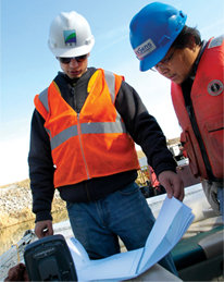
Monitoring Turbidity at Dredging Sites
Why Monitoring Matters
Dredging is a common and economically viable solution for the removal and subsequent treatment of contaminated sediment. If executed properly, dredging can yield positive environmental results without harming water quality conditions. Dredging operations should aim to remove sediment as efficiently as possible while diminishing short-term environmental impacts, most notably the re-suspension of potentially contaminated sediments.
To minimize sediment re-suspension and contaminant release, a monitoring system should be established. Sediment can easily be dislodged by dredging and dispersed into the water column. This re-suspension may damage water quality both in the immediate vicinity as well as downstream as it travels with the current. Additionally, if the suspended sediment is contaminated, it can release toxins into the water and air. Effective monitoring of re-suspended sediments for the duration of dredging operations is crucial to maintaining acceptable water quality levels for both wildlife and humans.
For this reason, the U.S. Army Corps of Engineers (USACE) and Environmental Protection Agency (EPA) offer extensive guidelines for estimating the environmental consequences of a dredge. The guides also emphasize the need to monitor these effects as the dredging operation occurs in order to keep any re-suspension and transport under control. These monitoring efforts allow project managers to respond if re-suspended sediment levels exceed pre-established parameters by slowing down or altering the dredging.
Read the complete USACE’s Technical Guidelines for Environmental Dredging of Contaminated Sediments
Read the complete EPA’s Contaminated Sediment Remediation Guidance for Hazardous Waste Sites
Environmental Dredging: Overview of USACE Guidelines
 Environmental dredging is defined as: “the removal of contaminated sediments from a water body for purposes of sediment remediation” (USACE). While there are several approaches to dealing with contaminated sediment, dredging is frequently the cleanup method of choice for projects under the Comprehensive Environmental Response, Compensation, and Liability Act (CERCLA), also known as the “Superfund” program.
As no two projects are identical, the specific environmental limits set for a dredging project will vary. Several influencing factors include location, sediment composition, acting regulatory agencies, and environmental laws. To assist with this effort, the U.S. Army Corps of Engineers (USACE) has generated a comprehensive set of guidelines to evaluate environmental dredging as a solution for sediment remediation projects. While the EPA’s remediation guide addresses all possible steps and alternatives for dealing with contaminated sediment, the USACE’s guide focuses specifically on the dredging component.
These guidelines provide detailed steps regarding the establishment of a dredging operation, from the preliminary evaluation to the process, methods and control procedures. In doing so, this guide establishes a hierarchy of objectives regarding the technical aspects of a remedial dredging operation. These objectives aim not only to minimize sediment re-suspension, release, and residuals, but also to maintain a cost-effective strategy in both the short and long term.
Both of these guidelines stress the importance of implementing a monitoring strategy that provides rapid feedback, allowing dredge operators to respond to high re-suspension levels before they become problematic. Established limits for sediment re-suspension (maximum allowable levels for water quality and released contaminants), may be a part of dredging regulations established in consultation with stakeholders, or by federal acts and regulatory agencies.
The USACE recommends drafting a comprehensive monitoring plan that includes equipment and techniques to use, protocols for sampling, where to place sampling devices, and details about how to interpret the monitoring data. Furthermore, the guidelines suggest creating a management plan that describes the specific actions to be taken based on the results of the monitoring. This may include increasing monitoring locations/sampling frequency to further assess impacts, implementing operational controls (i.e., stopping or slowing down dredge work), altering debris management, or changing equipment. To this end, the USACE technical guidelines advise incorporating real-time feedback on re-suspension into the monitoring plan to make early identification of problems possible. The most rapid and efficient management responses are achievable with this real-time data.
A Real-Time Solution
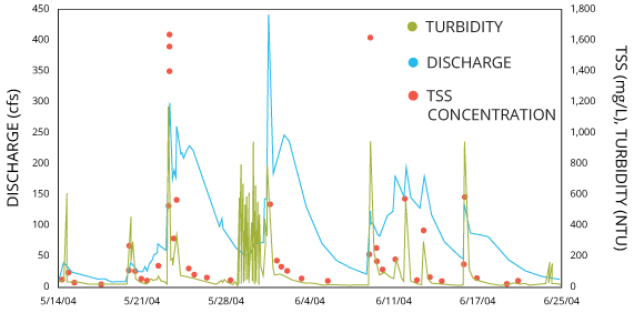 Measuring total suspended solids (TSS) directly is the best method for evaluating sediment concentrations. However, it is not feasible for real-time applications such as monitoring sediment re-suspension during dredging operations. At present, TSS can only be accurately measured by collecting water samples and conducting laboratory tests, which require filtering the sediment from the water, drying and weighing it. This procedure is too time-consuming for monitoring dredge sites, considering the quick feedback required to allow timely control measures. This is particularly true in cases when the dredged sediment contains contaminants that pose an added risk to wildlife and people. To achieve this real-time monitoring, turbidity, a measure of water clarity, is substituted for TSS.
Learn more in the Measuring Turbidity section.
Turbidity Technology
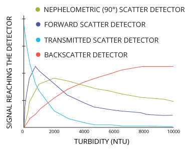
The most commonly used turbidity monitoring systems will use a submersible sensor to monitor for sediment re-suspension. These turbidity sensors can use nephelometry or backscatter technology to measure the amount of light scattered by particles in the water.
Regardless of the sensor chosen, it is important to use the same sensor model throughout a project for internally consistent data. While inter-instrument relationship models can be developed, data from different instrument designs are not directly comparable. Each sensor will read varying amounts of light scatter from suspended particles due to the differences in light source and measurement angle. In turn, the sensors will output varying results despite measuring the same water sample. In addition to cost considerations, sensor choice should be based on expected or potential turbidity readings (low, high, or a wide range), and whether or not compliant and comparable data would be useful.
Learn more in the Measuring Turbidity section.
Typical Turbidity Monitoring System
When dredging, it is necessary to monitor sediment re-suspension levels to prevent damage to the local ecosystem and minimize the spread of contaminants. This is usually done with a turbidity monitoring station upstream (for background data) and two stations downstream (at locations affected by the dredging).
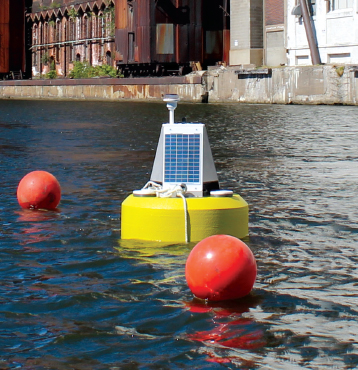
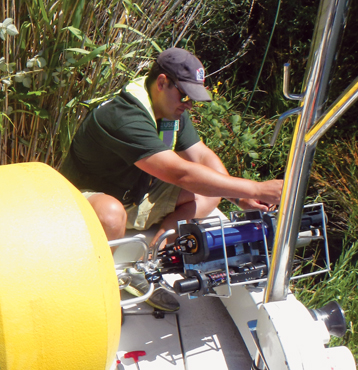
To be effective, measurement data should be provided in real time. The easiest and most efficient way to do this is with a buoy-based turbidity monitoring system. A data buoy can house sensors at multiple depths in the deepest part of the waterway, providing more comprehensive data than a shore-based system. This system can then securely transmit the data to the Internet in real time for access from any computer.
Buoy systems are flexible and customizable based on the dredging project requirements. They can house as many sensors as needed, and all equipment is powered via a marine battery and recharging solar panel system. With multiple telemetry options to choose from, continuous real-time data are available from any computer. This ensures that the dredging operations progress smoothly, and any control measures can be implemented immediately if parameter limits are exceeded.
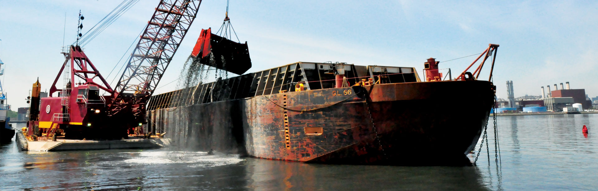
Dredge
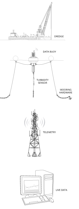 Dredges are excavators used to remove contaminated sediment from the water. They can be hydraulic, mechanical, or a hybrid. Most are mounted on a spud barge. An additional barge may be needed for sediment disposal.
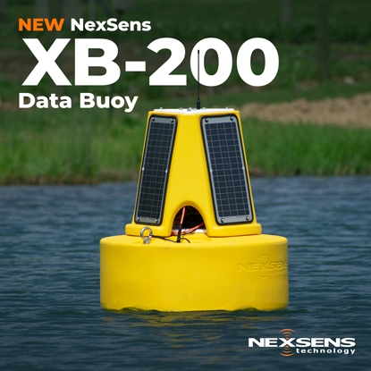
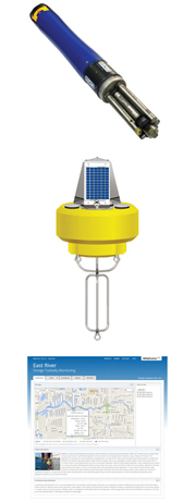
Data Buoy
A data buoy is a floating platform that supports real-time monitoring instruments such as sensors and data loggers. In addition to housing the monitoring equipment, the buoy supplies all power and can transmit sensor data in real time.
Mooring Hardware
Data buoys can be anchored with a single or two-point mooring based on application requirements.
Turbidity Sensor
Turbidity data are substituted for TSS as it can be measured instantaneously. Most turbidity sensors are compliant with ISO 7027 and have a wiper to prevent fouling. Sensors can hang at multiple levels in the water column, alone or in a multi-parameter sonde.
Telemetry
Telemetry provides access to data in real time. The wireless communication can be radio-to-shore, cellular or satellite based.
Live Data
24/7 instant access to project data is available through a cloud-based datacenter. Monitoring data can be viewed in real time, or as a graph to see trends. Real-time automated alerts can be sent via text or email when turbidity levels exceed pre-defined limits.
Points of Compliance
Where turbidity monitoring systems should be located will depend largely on the site conditions of the dredging project. The number of monitoring locations required for a dredging operation can vary, but a common monitoring setup relies on three measurement locations. The chosen measurement locations are known as points of compliance. At these points, the USACE suggests using stationary or towed turbidity sensors in conjunction with water column sampling.
Selecting the Location
As suggested by the name, stationary systems are set at fixed locations. These systems can be placed on structure or on an anchored buoy in the water. Seawalls are a common example of a structure that can be used, as turbidity monitoring sensors can be mounted in a perforated PVC pipe along the seawall. However, site conditions often make it difficult or impractical to mount the monitoring equipment along the shore. In addition, relying solely on shoreline solutions may not accurately represent re-suspension levels and sediment transport due to the nature of water currents. For these reasons, buoy-based systems offer the most comprehensive and cost-effective solution. Data buoys provide a stable platform for turbidity monitoring, with the ability to house multiple sensors at different depths in the water column. In addition, they can carry a data logger, solar-powered battery pack, and telemetry (wireless communications) systems for extended deployments.
Anchored buoys are usually located both up and downstream of the dredging operation. The downstream buoy(s) measure re-suspended sediment and sediment transport in areas at risk, while the upstream (and off-site) buoy serves as a control for suitable turbidity levels. These buoys can come in different sizes based on the environmental conditions and the number of sensors suspended from the buoy. Data buoys with 150- to 450-lb. net buoyancy are generally adequate for monitoring projects on rivers, inland lakes, and protected waters. Larger platforms may be required in coastal and Great Lakes deployments that are subject to more extreme conditions and wave action.
Towed sensors are known as “floating” points of compliance, as they move with the dredging operation. While these can be attached directly to the dredging equipment, they can also be deployed on a buoy system a set distance away from the dredge location. The buoy systems then move with the dredge as the project progresses, remaining the same distance away from the active dredging site.
Pre-Deployment
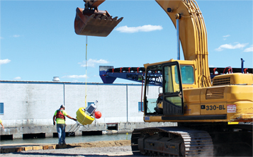 For accurate data, all sensors should be calibrated shortly before the project begins. If using a buoy-based system, the platforms should be fully assembled on shore prior to deployment. This includes attaching any sensors, towers, solar panels, and additional ballast weights if needed. Furthermore, the complete turbidity monitoring system (sensors, data logger, telemetry, software) should be tested before the buoy is put in the water. While this process ensures that all equipment is functioning within specifications, it also gives everyone the chance to familiarize themselves with the system prior to deployment. Issues are always easier to deal with before the buoy platform is deployed in the water.
Buoy Mooring
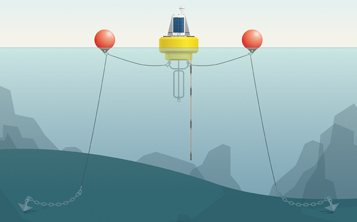
A buoy-based system must be moored to ensure that it remains stationary. It is recommended to moor the buoy in the deepest part of the waterway to ensure the most inclusive measurements. This allows for multiple measurement depths and will best reflect the characteristics of the water body as a whole. Buoy-based systems are typically moored as either a single-point or two-point mooring, based on environmental and application-specific factors.
Learn more in the Buoy Mooring section.
Data Management
 A major part of any monitoring project is collecting and accessing the data. While it is possible to simply record measurements onsite, the ability to log, send and view monitoring data in real time is far more efficient.
Learn more in the Monitoring Equipment section.
Quality Assurance
Accurate data ensure that dredging operations remain in compliance with set regulations. To maintain that accuracy and keep equipment functioning within specifications, best practice recommends cleaning and calibrating the instruments at regular intervals. It is also recommended to cross-check sensor accuracy against a separate instrument. This cross-checked data can then be used to show compliance against an EPA-approved method, if needed.
System Maintenance
 Regardless of the turbidity equipment chosen to monitor a dredging site, periodic maintenance and calibration is required. Instrument maintentence includes cleaning the instruments (especially if a sensor is not self-wiping), and replacing any deteriorating o-rings to prevent water ingress. If using additional parameter sensors (such as conductivity), further field servicing may be required. Maintenance intervals are largely dependent on site conditions and other variables, such as the potential for biofouling. Common calibration and maintenance intervals are on a weekly or bi-weekly basis.
Turbidity sensors usually require a two-point calibration — one at 0 NTU/FNU and another at a higher turbidity value (often 126 NTU/124 FNU). The 0 NTU value can be obtained using de-ionized water, though 0 NTU/FNU standard solutions do exist. The high range calibration should use an approved standard such as a commercial or prepared Formazin, or commercial AMCO-AEPA standards. For greater accuracy and a wider range, turbidity sensors can follow a three-point calibration (e.g. 0 NTU, 100 NTU, and 1000 NTU). Regardless of the number of points used, it is important to always include 0 NTU/FNU as the first point. For best results, use only freshly prepared or purchased turbidity standard, as they degrade over time. Any diluted standard should only be used on the day it is made.
In case of sensor failure or damage, it is useful to have spare sensors or sondes on hand. These can be field swapped during calibration or routine maintenance checks. Having a spare turbidity sensor available will reduce downtime due to unforeseen sensor failure, which could cause critical and costly interruptions to safe dredging operations.
For greater details regarding maintenance requirements and sensor calibration, the manufacturer’s user manual should be referenced.
Performance Verification
 In addition to keeping turbidity equipment calibrated, it’s important to periodically verify that the sensors are providing accurate turbidity data. The best way to achieve this is by checking turbidity in the same area using a separate, portable monitoring system. This is also known as spot sampling.
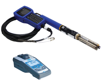
There are two portable turbidity measurement methods available for spot sampling. The first method uses a sensor (much like the one used in the buoy-based monitoring system) and a handheld display. The turbidity sensor can be attached directly to a handheld display or through a sonde to the display to show real-time data. Sondes are useful instruments if other parameters, such as pH, dissolved oxygen, or conductivity should be recorded as well. The sonde or sensor can be lowered into the water column to a depth that matches the in-place sensors. While it is at that depth, a turbidity measurement can be taken. The data from this portable system can then be compared to the in-place monitoring system and checked for discrepancies. As with the buoy-based system, this method reports in FNU or FBU based on the sensor used. While FNU readings are approved by ISO 7027, neither option is approved by the EPA.
The second method uses a handheld turbidity meter. This method requires taking a water sample, and then inserting it into the meter for a reading. As this method uses a sample instead of an in-situ measurement, it is often not representative of the surface water as a whole. This is especially a hindrance when quality checking monitoring systems that measure turbidity at multiple depths along the water column. While handheld meters are not submersible, many styles are compliant with EPA method 180.1. This means that the long-term data can be cross-checked against an EPA approved method. However, while correlations can be made between data sets, care should be taken when comparing data between the meter and the buoy-based monitoring system. Turbidity instruments are inherently not comparable, and comparative models are only accurate for the specific sample location.
Recommended Equipment
 While there are plenty of turbidity monitoring instruments on the market, some stand out above the rest. Fondriest Environmental has selected these products as the best in their field for their quality, reliability and value. Together, they provide an advanced and powerful real-time turbidity monitoring system. For a sensor or sonde, accuracy is of utmost importance and the YSI EXO2 does not disappoint. The rugged NexSens CB-450 offers long-term durability with 30 W of solar power, 450 pounds of buoyancy and a choice of instrument mounts for multiple sensors. Alone, real-time data are good, but with remote data collection, 24/7 access from any computer, instant alarm notifications and trend tracking, the intuitive WQData LIVE takes real-time data to the next level.
Learn more about these products:
- YSI EXO2 Multi-Parameter Water Quality Sonde
- NexSens CB-450 Data Buoy
- NexSens WQData LIVE Web Datacenter
Cite This Work
Fondriest Environmental, Inc. “Monitoring Turbidity at Dredging Sites.” Fundamentals of Environmental Measurements. 23 Oct. 2014. Web. < https://www.fondriest.com/environmental-measurements/environmental-monitoring-applications/monitoring-turbidity-at-dredging-sites/ >.